
Using the Signal API
The signal API provides an intermediate access point within the Faust compilation chain. In this tutorial, we present it through code examples. The goal is to show how new audio DSP languages (textual or graphical) could be built on top of the signal API, and take advantage of part of the Faust compiler infrastructure.
Faust compiler structure
The Faust compiler is composed of several steps:
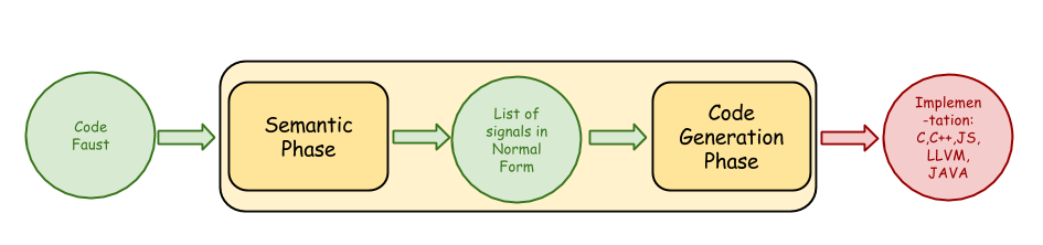
Starting from the DSP source code, the Semantic Phase produces signals as conceptually infinite streams of samples or control values. Those signals are then compiled in imperative code (C/C++, LLVM IR, WebAssembly, etc.) in the Code Generation Phase.
The Semantic Phase itself is composed of several steps:
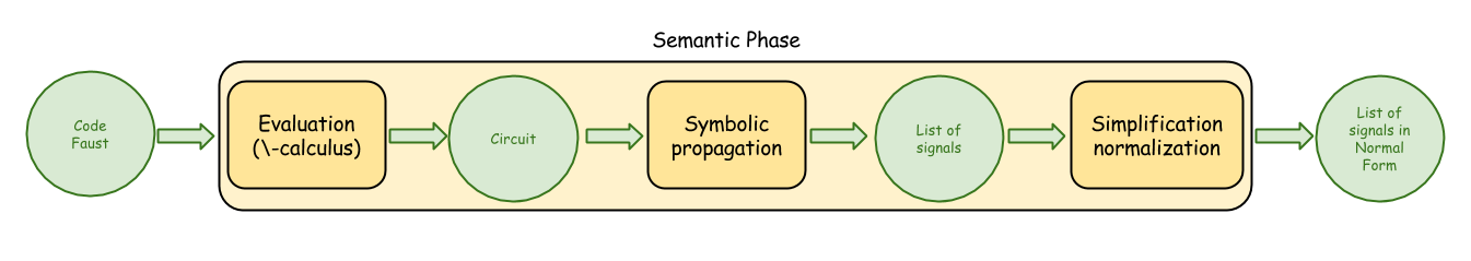
The initial DSP code using the Block Diagram Algebra (BDA) is translated into a flat circuit in normal form in the Evaluation, lambda-calculus step.
The list of output signals is produced by the Symbolic Propagation step. Each output signal is then simplified and a set of optimizations are done (normal form computation and simplification, delay line sharing, typing, etc.) to finally produce a list of output signals in normal form.
The Code Generation Phase translates the signals into an intermediate representation named FIR (Faust Imperative Representation), which is then converted to the final target language (C/C++, LLVM IR, WebAssembly, etc.) with a set of backends.
Accessing the signal stage
A new intermediate public entry point has been created in the Semantic Phase to allow the creation of a signal set (as a list of output signals), and then benefit from all remaining parts of the compilation chain. The signal API (or the C signal API version) allows developers to programmatically create the list of output signals and then compile it to create a ready-to-use DSP as a C++ class, or LLVM, Interpreter, or WebAssembly factories, to be used with all existing architecture files. Several optimizations done at the signal stage will be demonstrated by looking at the generated C++ code.
Note that the box API allows access to another stage in the compilation chain.
Compiling signal expressions
To use the signal API, the following steps must be taken:
-
creating a global compilation context using the
createLibContextfunction -
creating signal outputs using the signal API, progressively building more complex expressions by combining simpler ones
-
compiling the list of outputs using the
createCPPDSPFactoryFromSignalsfunction to create a DSP factory (or createDSPFactoryFromSignals to generate an LLVM embedding factory, or createInterpreterDSPFactoryFromSignals to generate an Interpreter embedding factory) -
finally destroying the compilation context using the
destroyLibContextfunction
The DSP factories allow the creation of DSP instances, to be used with audio and UI architecture files, outside of the compilation process itself. The DSP instances and factory will finally have to be deallocated when they are no longer used.
Tools
Let's first define a compile function, which uses the createCPPDSPFactoryFromSignals function and prints the generated C++ class:
static void compile(const string& name,
                    tvec signals,
                    int argc = 0,
                    const char* argv[] = nullptr)
{
    string error_msg;
    dsp_factory_base* factory = createCPPDSPFactoryFromSignals(name,
                                                              signals,
                                                              argc,
                                                              argv,
                                                              error_msg);
    if (factory) {
        // Print the C++ class
        factory->write(&cout);
        delete(factory);
    } else {
        cerr << error_msg;
    }
}
A macro to wrap all the needed steps:
#define COMPILER(exp)    \
{                        \
    createLibContext();  \
    exp                  \
    destroyLibContext(); \
}                        \
Examples
For each example, the equivalent Faust DSP program and SVG diagram is given as helpers. The SVG diagram shows the result of the compilation propagate step (so before any of the signal normalization steps) and clearly shows how each output signal expression has to be created. All presented C++ examples (as well as some more) are defined in the signal-tester tool, to be compiled with make signal-tester in the tools/benchmark folder.
Simple constant signal
Let's create a program generating the 0.5 constant value. Here is the Faust DSP code:

The following code creates a vector of output signals (with the tvec type), containing the single sigReal(0.5) signal, then compile it and display the C++ class:
static void test1()
{
    COMPILER
    (
        tvec signals;
        signals.push_back(sigReal(0.5));

        compile("test1", signals);
    )
}
The compute method is then:
virtual void compute(int count, FAUSTFLOAT** inputs, FAUSTFLOAT** outputs)
{
    FAUSTFLOAT* output0 = outputs[0];
    for (int i0 = 0; (i0 < count); i0 = (i0 + 1)) {
        output0[i0] = FAUSTFLOAT(0.5f);
    }
}
Doing some mathematical operations on an input signal
Here is a simple program doing a mathematical operation on a signal input:

The first audio input is created with sigInput(0) signal, then transformed using sigAdd and sigMul signal operators to produce two outputs:
static void test2()
{
    COMPILER
    (
        tvec signals;
        Signal in1 = sigInput(0);
        signals.push_back(sigAdd(in1, sigReal(0.5)));
        signals.push_back(sigMul(in1, sigReal(1.5)));

        compile("test2", signals);
     )
}
The compute method is then:
virtual void compute(int count, FAUSTFLOAT** inputs, FAUSTFLOAT** outputs)
{
    FAUSTFLOAT* input0 = inputs[0];
    FAUSTFLOAT* output0 = outputs[0];
    FAUSTFLOAT* output1 = outputs[1];
    for (int i0 = 0; (i0 < count); i0 = (i0 + 1)) {
        float fTemp0 = float(input0[i0]);
        output0[i0] = FAUSTFLOAT((fTemp0 + 0.5f));
        output1[i0] = FAUSTFLOAT((1.5f * fTemp0));
    }
}
Note that accessing input N is simply done using the sigInput(N) expression.
Defining delayed signals
Here is a simple program using a signal input and doing mathematical operations on it, then delaying the signals:

The sigDelay(x, y) operator is used to delay the x first parameter with the second y parameter, here with constant values:
static void test3()
{
    COMPILER
    (
        tvec signals;
        Signal in1 = sigInput(0);
        signals.push_back(sigDelay(sigAdd(in1, sigReal(0.5)), sigInt(500)));
        signals.push_back(sigDelay(sigMul(in1, sigReal(1.5)), sigInt(3000)));

        compile("test3", signals);
    )
}
The compute method is then:
virtual void compute(int count, FAUSTFLOAT** inputs, FAUSTFLOAT** outputs)
{
    FAUSTFLOAT* input0 = inputs[0];
    FAUSTFLOAT* output0 = outputs[0];
    FAUSTFLOAT* output1 = outputs[1];
    for (int i0 = 0; (i0 < count); i0 = (i0 + 1)) {
        float fTemp0 = float(input0[i0]);
        fVec0[(IOTA & 4095)] = fTemp0;
        fVec1[(IOTA & 511)] = (fTemp0 + 0.5f);
        output0[i0] = FAUSTFLOAT(fVec1[((IOTA - 500) & 511)]);
        output1[i0] = FAUSTFLOAT((1.5f * fVec0[((IOTA - 3000) & 4095)]));
        IOTA = (IOTA + 1);
    }
}
Several options of the Faust compiler allow control of the generated C++ code. By default computation is done sample by sample in a single loop. But the compiler can also generate vector and parallel code. The following code show how to compile in vector mode:
static void test5()
{
    createLibContext();

    tvec signals;
    Signal in1 = sigInput(0);
    signals.push_back(sigDelay(sigAdd(in1, sigReal(0.5)), sigInt(500)));
    signals.push_back(sigDelay(sigMul(in1, sigReal(1.5)), sigInt(3000)));

    // Vector compilation
    compile("test5", signals, 3, (const char* []){ "-vec", "-lv", "1" });

    destroyLibContext();
}
The compute method is then:
virtual void compute(int count, FAUSTFLOAT** inputs, FAUSTFLOAT** outputs)
{
    FAUSTFLOAT* input0_ptr = inputs[0];
    FAUSTFLOAT* output0_ptr = outputs[0];
    FAUSTFLOAT* output1_ptr = outputs[1];
    for (int vindex = 0; (vindex < count); vindex = (vindex + 32)) {
        FAUSTFLOAT* input0 = &input0_ptr[vindex];
        FAUSTFLOAT* output0 = &output0_ptr[vindex];
        FAUSTFLOAT* output1 = &output1_ptr[vindex];
        int vsize = std::min<int>(32, (count - vindex));
        /* Vectorizable loop 0 */
        /* Pre code */
        fYec0_idx = ((fYec0_idx + fYec0_idx_save) & 4095);
        /* Compute code */
        for (int i = 0; (i < vsize); i = (i + 1)) {
            fYec0[((i + fYec0_idx) & 4095)] = float(input0[i]);
        }
        /* Post code */
        fYec0_idx_save = vsize;
        /* Vectorizable loop 1 */
        /* Pre code */
        fYec1_idx = ((fYec1_idx + fYec1_idx_save) & 1023);
        /* Compute code */
        for (int i = 0; (i < vsize); i = (i + 1)) {
            fYec1[((i + fYec1_idx) & 1023)] = (float(input0[i]) + 0.5f);
        }
        /* Post code */
        fYec1_idx_save = vsize;
        /* Vectorizable loop 2 */
        /* Compute code */
        for (int i = 0; (i < vsize); i = (i + 1)) {
            output0[i] = FAUSTFLOAT(fYec1[(((i + fYec1_idx) - 500) & 1023)]);
        }
        /* Vectorizable loop 3 */
        /* Compute code */
        for (int i = 0; (i < vsize); i = (i + 1)) {
            output1[i] = FAUSTFLOAT((1.5f * fYec0[(((i + fYec0_idx) - 3000) & 4095)]));
        }
    }
}
And can possibly be faster if the C++ compiler can auto-vectorize it.
If the delay operators are used on the input signal before the mathematical operations, then a single delay line will be created, taking the maximum size of both delay lines:

And built with the following code:
static void test4()
{
    COMPILER
    (
        tvec signals;
        Signal in1 = sigInput(0);
        signals.push_back(sigAdd(sigDelay(in1, sigInt(500)), sigReal(0.5)));
        signals.push_back(sigMul(sigDelay(in1, sigInt(3000)), sigReal(1.5)));

        compile("test4", signals);
    )
}
In the compute method, the single fVec0 delay line is read at 2 differents indexes:
virtual void compute(int count, FAUSTFLOAT** inputs, FAUSTFLOAT** outputs)
{
    FAUSTFLOAT* input0 = inputs[0];
    FAUSTFLOAT* output0 = outputs[0];
    FAUSTFLOAT* output1 = outputs[1];
    for (int i0 = 0; (i0 < count); i0 = (i0 + 1)) {
        float fTemp0 = float(input0[i0]);
        fVec0[(IOTA & 4095)] = fTemp0;
        output0[i0] = FAUSTFLOAT((fVec0[((IOTA - 500) & 4095)] + 0.5f));
        output1[i0] = FAUSTFLOAT((1.5f * fVec0[((IOTA - 3000) & 4095)]));
        IOTA = (IOTA + 1);
    }
}
Equivalent signal expressions
It is really important to note that syntactically equivalent signal expressions will be internally represented by the same memory structure (using hash consing), thus treated in the same way in the further compilation steps. So the following code where the s1 variable is created to define the sigAdd(sigDelay(sigInput(0), sigInt(500)), sigReal(0.5)) expression, then used in both outputs:
static void equivalent1()
{
    COMPILER
    (
        tvec signals;
        Signal s1 = sigAdd(sigDelay(sigInput(0), sigInt(500)), sigReal(0.5))
        signals.push_back(s1);
        signals.push_back(s1);

        compile("equivalent1", signals);
    )
}
Will behave exactly the same as the following code, where the sigAdd(sigDelay(sigInput(0), sigInt(500)), sigReal(0.5)) expression is used twice:
static void equivalent2()
{
    COMPILER
    (
        tvec signals;
        signals.push_back(sigAdd(sigDelay(sigInput(0), sigInt(500)), sigReal(0.5)));
        signals.push_back(sigAdd(sigDelay(sigInput(0), sigInt(500)), sigReal(0.5)));

        compile("equivalent2", signals);
    )
}
It can be a property to remember when creating a DSL on top of the signal API.
Using User Interface items
User Interface items can be used, as in the following example, with a vslider:

Built with the following code:
static void test8()
{
    COMPILER
    (
        tvec signals;
        Signal in1 = sigInput(0);
        Signal s = sigVSlider("Vol", sigReal(0.5), sigReal(0.), sigReal(1.), sigReal(0.01));
        signals.push_back(sigMul(s, sigDelay(sigAdd(in1, sigReal(0.5)), sigInt(500))));

        compile("test8", signals);
    )
}
The buildUserInterface method is generated, using the fVslider0 variable:
virtual void buildUserInterface(UI* ui_interface)
{
        ui_interface->openVerticalBox("test8");
        ui_interface->addVerticalSlider("Vol", &fVslider0,
                                    FAUSTFLOAT(0.5f),
                                    FAUSTFLOAT(0.0f),
                                    FAUSTFLOAT(1.0f),
                                    FAUSTFLOAT(0.00999999978f));
        ui_interface->closeBox();
}
The compute method is then:
virtual void compute(int count, FAUSTFLOAT** inputs, FAUSTFLOAT** outputs)
{
        FAUSTFLOAT* input0 = inputs[0];
        FAUSTFLOAT* output0 = outputs[0];
        float fSlow0 = float(fVslider0);
        for (int i0 = 0; (i0 < count); i0 = (i0 + 1)) {
            fVec0[(IOTA & 511)] = (float(input0[i0]) + 0.5f);
            output0[i0] = FAUSTFLOAT((fSlow0 * fVec0[((IOTA - 500) & 511)]));
            IOTA = (IOTA + 1);
        }
}
User Interface layout can be described with hgroup, or vgroup or tgroup. With the signal API, the layout can be defined using the labels-as-pathnames syntax, as in the following example:

Built with the following code:
static void test9()
{
    COMPILER
    (
        tvec signals;
        Signal freq = sigVSlider("h:Oscillator/freq",
                                 sigReal(440), sigReal(50),
                                 sigReal(1000), sigReal(0.1));
        Signal gain = sigVSlider("h:Oscillator/gain",
                                 sigReal(0), sigReal(0),
                                 sigReal(1), sigReal(0.011));
        signals.push_back(sigMul(freq, sigMul(gain, sigInput(0))));

        compile("test9", signals);
    )
}
The buildUserInterface method is generated with the expected openHorizontalBox call:
virtual void buildUserInterface(UI* ui_interface)
{
    ui_interface->openHorizontalBox("Oscillator");
    ui_interface->addVerticalSlider("freq", &fVslider0,
                                    FAUSTFLOAT(440.0f),
                                    FAUSTFLOAT(50.0f),
                                    FAUSTFLOAT(1000.0f),
                                    FAUSTFLOAT(0.100000001f));
    ui_interface->addVerticalSlider("gain", &fVslider1,
                                    FAUSTFLOAT(0.0f),
                                    FAUSTFLOAT(0.0f),
                                    FAUSTFLOAT(1.0f),
                                    FAUSTFLOAT(0.0109999999f));
    ui_interface->closeBox();
}
Defining recursive signals
Recursive signals can be defined using the sigRecursion function to build the recursion, and the sigSelf function to refer to the recursive signal itself. A one sample delay is automatically created to produce a valid computation. Here is a simple example:

Built with the following code:
static void test10()
{
    COMPILER
    (
        tvec signals;
        Signal in1 = sigInput(0);
        signals.push_back(sigRecursion(sigAdd(sigSelf(), in1)));

        compile("test10", signals);
    )
}
The compute method shows the fRec0variable that keeps the delayed signal:
virtual void compute(int count, FAUSTFLOAT** inputs, FAUSTFLOAT** outputs)
{
        FAUSTFLOAT* input0 = inputs[0];
        FAUSTFLOAT* output0 = outputs[0];
        for (int i0 = 0; (i0 < count); i0 = (i0 + 1)) {
            fRec0[0] = (float(input0[i0]) + fRec0[1]);
            output0[i0] = FAUSTFLOAT(fRec0[0]);
            fRec0[1] = fRec0[0];
        }
}
The same equivalent code can be defined using the more general sigRecursionN and sigSelfN functions which allow to build a list of (possibly mutually dependent) recursive signals:
static void test10bis()
{
    COMPILER
    (
        tvec signals;
        Signal in1 = sigInput(0);
        signals.push_back(sigRecursionN(sigAdd(sigSelfN(0), in1)));

        compile("test10", signals);
    )
}
Here is an example of the definition of mutually dependent recursive signals:
static void test10ter()
{
    COMPILER
    (
        Signal in0 = sigInput(0);
        Signal in1 = sigInput(1);
        tvec ins;
        ins.push_back(sigAdd(sigMul(sigSelfN(1), sigReal(0.5)), in0));
        ins.push_back(sigAdd(sigMul(sigSelfN(0), sigReal(0.9)), in1));
        tvec outs = sigRecursionN(ins);

        compile("test10ter", outs);
    )
}
With the following compute method:
virtual void compute(int count, FAUSTFLOAT** RESTRICT inputs, FAUSTFLOAT** RESTRICT outputs) {
    FAUSTFLOAT* input0 = inputs[0];
    FAUSTFLOAT* input1 = inputs[1];
    FAUSTFLOAT* output0 = outputs[0];
    FAUSTFLOAT* output1 = outputs[1];
    for (int i0 = 0; i0 < count; i0 = i0 + 1) {
        fRec0[0] = float(input0[i0]) + 0.5f * fRec1[1];
        fRec1[0] = float(input1[i0]) + 0.9f * fRec0[1];
        output0[i0] = FAUSTFLOAT(fRec0[0]);
        output1[i0] = FAUSTFLOAT(fRec1[0]);
        fRec0[1] = fRec0[0];
        fRec1[1] = fRec1[0];
    }
}
Accessing the global context
In Faust, the underlying audio engine sample rate and buffer size is accessed using the foreign function and constant mechanism. The values can also be used in the signal language with the following helper functions:
// Reproduce the 'SR' definition in platform.lib
// SR = min(192000.0, max(1.0, fconstant(int fSampleFreq, <dummy.h>)));
inline Signal SR()
{
    return sigMin(sigReal(192000.0),
           sigMax(sigReal(1.0),
           sigFConst(SType::kSInt, "fSampleFreq", "<dummy.h>")));
}

// Reproduce the 'BS' definition in platform.lib
// BS = fvariable(int count, <dummy.h>);
inline Signal BS()
{
    return sigFVar(SType::kSInt, "count", "<dummy.h>");
}
So the following DSP program:

Can be written at the signal API level with:
static void test11()
{
    COMPILER
    (
        tvec signals;
        signals.push_back(SR());
        signals.push_back(BS());

        compile("test11", signals);
    )
}
And the resulting C++ class contains:
virtual void instanceConstants(int sample_rate)
{
    fSampleRate = sample_rate;
    fConst0 = std::min<float>(192000.0f, std::max<float>(1.0f, float(fSampleRate)));
}
and:
virtual void compute(int count, FAUSTFLOAT** inputs, FAUSTFLOAT** outputs)
{
    FAUSTFLOAT* output0 = outputs[0];
    FAUSTFLOAT* output1 = outputs[1];
    int iSlow0 = count;
    for (int i0 = 0; (i0 < count); i0 = (i0 + 1)) {
        output0[i0] = FAUSTFLOAT(fConst0);
        output1[i0] = FAUSTFLOAT(iSlow0);
    }
}
Creating tables
Read only and read/write tables can be created. The read only table signal is created with sigReadOnlyTable and takes:
- a size first argument
- a content second argument
- a read index third argument (between 0 and size-1)
and produces the indexed table content as its single output. The following simple DSP example:

Can be written with the code:
static void test20()
{
    COMPILER
    (
        tvec signals;
        signals.push_back(sigReadOnlyTable(sigInt(10), sigInt(1), sigIntCast(sigInput(0))));

        compile("test20", signals);
    )
}
The resulting C++ code contains the itbl0mydspSIG0 static table definition:
static int itbl0mydspSIG0[10];
The table filling code that will be called once at init time:
void fillmydspSIG0(int count, int* table)
{
    for (int i1 = 0; (i1 < count); i1 = (i1 + 1)) {
        table[i1] = 1;
    }
}
An the compute method that access the itbl0mydspSIG0 table:
virtual void compute(int count, FAUSTFLOAT** inputs, FAUSTFLOAT** outputs)
{
    FAUSTFLOAT* input0 = inputs[0];
    FAUSTFLOAT* output0 = outputs[0];
    for (int i0 = 0; (i0 < count); i0 = (i0 + 1)) {
        output0[i0] = FAUSTFLOAT(itbl0mydspSIG0[int(float(input0[i0]))]);
    }
}
The read/write table signal is created with sigWriteReadTable and takes:
- a size first argument
- a content second argument
- a write index a third argument (between 0 and size-1)
- the input of the table as fourth argument
- a read index as fifth argument (between 0 and size-1)
and produces the indexed table content as its single output. The following DSP example:

Can be written with the code:
static void test20()
{
    COMPILER
    (
        tvec signals;
        signals.push_back(sigWriteReadTable(sigInt(10),
                                            sigInt(1),
                                            sigIntCast(sigInput(0)),
                                            sigIntCast(sigInput(1)),
                                            sigIntCast(sigInput(2))));

        compile("test21", signals);
    )
}
The resulting C++ code contains the itbl0 definition as a field in the mydsp class:
int itbl0[10];
The table filling code that will be called once at init time:
void fillmydspSIG0(int count, int* table)
{
    for (int i1 = 0; (i1 < count); i1 = (i1 + 1)) {
        table[i1] = 1;
    }
}
An the compute method that reads and writes in the itbl0 table:
virtual void compute(int count, FAUSTFLOAT** inputs, FAUSTFLOAT** outputs)
{
    FAUSTFLOAT* input0 = inputs[0];
    FAUSTFLOAT* input1 = inputs[1];
    FAUSTFLOAT* input2 = inputs[2];
    FAUSTFLOAT* output0 = outputs[0];
    for (int i0 = 0; (i0 < count); i0 = (i0 + 1)) {
        itbl0[int(float(input0[i0]))] = int(float(input1[i0]));
        output0[i0] = FAUSTFLOAT(itbl0[int(float(input2[i0]))]);
    }
}
Creating waveforms
The following DSP program defining a waveform:

Can be written with the code, where the size of the waveform is the first output, and the waveform content itself is the second output created with sigWaveform, to follow the waveform semantic:
static void test12()
{
    COMPILER
    (
        tvec waveform;
        // Fill the waveform content vector
        for (int i = 0; i < 5; i++) {
            waveform.push_back(sigReal(100*i));
        }
        tvec signals;
        signals.push_back(sigInt(waveform.size())); // the waveform size
        signals.push_back(sigWaveform(waveform));   // the waveform content

        compile("test12", signals);
     )
}
With the resulting C++ code, where the fmydspWave0 waveform is defined as a static table:
const static float fmydspWave0[5] = {0.0f,100.0f,200.0f,300.0f,400.0f};
And using in the following compute method:
virtual void compute(int count, FAUSTFLOAT** inputs, FAUSTFLOAT** outputs)
{
    FAUSTFLOAT* output0 = outputs[0];
    FAUSTFLOAT* output1 = outputs[1];
    for (int i0 = 0; (i0 < count); i0 = (i0 + 1)) {
        output0[i0] = FAUSTFLOAT(5);
        output1[i0] = FAUSTFLOAT(fmydspWave0[fmydspWave0_idx]);
        fmydspWave0_idx = ((1 + fmydspWave0_idx) % 5);
    }
}
Creating Soundfiles
The soundfile primitive allows access to a list of externally defined sound resources, described as the list of their filenames or complete paths. It takes:
- the sound number (as a integer between 0 and 255 as a constant numerical expression)
- the read index in the sound (which will access the last sample of the sound if the read index is greater than the sound length)
The generated block has:
- two fixed outputs: the first one is the currently accessed sound length in frames, the second one is the currently accessed sound nominal sample rate
- several more outputs for the sound channels themselves, as a constant numerical expression
The soundfile block is created with sigSoundfile, but cannot be used directly. It has to be used with:
sigSoundfileLengthto access the sound length in framessigSoundfileRateto access the sound rate in HzsigSoundfileBufferto access the actual samples
Thus the following DSP code:

Will be created using the signal API with:
static void test19()
{
    COMPILER
    (
        tvec signals;
        // Soundfile definition
        Signal sf = sigSoundfile("sound[url:{'tango.wav'}]");
        // Simple read index of 0 to simplify the code
        Signal rdx = sigInt(0);
        // Part 0
        Signal part = sigInt(0);
        // Wrapped index to avoid reading outside the buffer
        Signal wridx = sigIntCast(sigMax(sigInt(0),
                       sigMin(rdx, sigSub(sigSoundfileLength(sf,
                       sigInt(0)),
                       sigInt(1)))));
        // Accessing part 0
        signals.push_back(sigSoundfileLength(sf, part));
        // Accessing part 0
        signals.push_back(sigSoundfileRate(sf, part));
        // Accessing chan 0 and part 0, with a wrapped read index
        signals.push_back(sigSoundfileBuffer(sf, sigInt(0), part, wridx));

        compile("test19", signals);
    )
}
And the following compute method is generated:
virtual void compute(int count, FAUSTFLOAT** inputs, FAUSTFLOAT** outputs)
{
    FAUSTFLOAT* output0 = outputs[0];
    FAUSTFLOAT* output1 = outputs[1];
    FAUSTFLOAT* output2 = outputs[2];
    Soundfile* fSoundfile0ca = fSoundfile0;
    int* fSoundfile0ca_le0 = fSoundfile0ca->fLength;
    int iSlow0 = fSoundfile0ca_le0[0];
    int* fSoundfile0ca_ra0 = fSoundfile0ca->fSR;
    int iSlow1 = fSoundfile0ca_ra0[0];
    int iSlow2 = std::max<int>(0, std::min<int>(0, (iSlow0 + -1)));
    int* fSoundfile0ca_of0 = fSoundfile0ca->fOffset;
    float** fSoundfile0ca_bu0 = static_cast<float**>(fSoundfile0ca->fBuffers);
    float* fSoundfile0ca_bu_ch0 = fSoundfile0ca_bu0[0];
    for (int i0 = 0; (i0 < count); i0 = (i0 + 1)) {
        output0[i0] = FAUSTFLOAT(iSlow0);
        output1[i0] = FAUSTFLOAT(iSlow1);
        output2[i0] = FAUSTFLOAT(fSoundfile0ca_bu_ch0[(fSoundfile0ca_of0[0] + iSlow2)]);
    }
    fSoundfile0 = fSoundfile0ca;
}
Defining more complex expressions: phasor and oscillator
More complex signal expressions can be defined, creating signals using auxiliary definitions. So the following DSP program:

Can be built using the following helper functions, here written in C:
static Signal decimalpart(Signal x)
{
    return sigSub(x, sigIntCast(x));
}

static Signal phasor(Signal f)
{
    return sigRecursion(decimalpart(sigAdd(sigSelf(), sigDiv(f, SR()))));
}
And the main function combining them:
static void test17()
{
    COMPILER
    (
        tvec signals;
        signals.push_back(phasor(sigReal(440.0)));

        compile("test17", signals);
    )
}
Which produces the following compute method:
virtual void compute(int count, FAUSTFLOAT** inputs, FAUSTFLOAT** outputs)
{
    FAUSTFLOAT* output0 = outputs[0];
    for (int i0 = 0; (i0 < count); i0 = (i0 + 1)) {
        fRec0[0] = (fConst0 + (fRec0[1] - float(int((fConst0 + fRec0[1])))));
        output0[i0] = FAUSTFLOAT(fRec0[0]);
        fRec0[1] = fRec0[0];
    }
}
Now the following oscillator:

Can be built with:
static Signal osc(Signal f)
{
    return sigSin(sigMul(phasor(f), sigMul(sigReal(2.0), sigReal(3.141592653))));
}

static void test18()
{
    COMPILER
    (
        tvec signals;
        signals.push_back(osc(sigReal(440.0)));
        signals.push_back(osc(sigReal(440.0)));

        compile("test18", signals);
    )
}
Which produces the following compute method, where one can see that since the same oscillator signal is used on both outputs, it is actually computed once and copied twice:
virtual void compute(int count, FAUSTFLOAT** inputs, FAUSTFLOAT** outputs)
{
    FAUSTFLOAT* output0 = outputs[0];
    FAUSTFLOAT* output1 = outputs[1];
    for (int i0 = 0; (i0 < count); i0 = (i0 + 1)) {
        fRec0[0] = (fConst0 + (fRec0[1] - float(int((fConst0 + fRec0[1])))));
        float fTemp0 = std::sin((6.28318548f * fRec0[0]));
        output0[i0] = FAUSTFLOAT(fTemp0);
        output1[i0] = FAUSTFLOAT(fTemp0);
        fRec0[1] = fRec0[0];
    }
}
Using the generated code
Using the LLVM or Interpreter backends makes it possible to generate and execute the compiled DSP on the fly.
The LLVM backend can be used with createDSPFactoryFromSignals (see llvm-dsp.h) to produce a DSP factory, then a DSP instance:
string error_msg;
llvm_dsp_factory* factory = createDSPFactoryFromSignals("FaustDSP",
                                                        signals, 0,
                                                        nullptr, "",
                                                        error_msg);
// Check factory
dsp* dsp = factory->createDSPInstance();
// Check dsp
...
// Use dsp
...
// Delete dsp and factory
delete dsp;
deleteDSPFactory(factory);
The Interpreter backend can be used with createInterpreterDSPFactoryFromSignals (see interpreter-dsp.h) to produce a DSP factory, then a DSP instance:
string error_msg;
interpreter_dsp_factory* factory = createInterpreterDSPFactoryFromSignals("FaustDSP",
                                                                          signals, 0,
                                                                          nullptr, "",
                                                                          error_msg);
// Check factory
dsp* dsp = factory->createDSPInstance();
// Check dsp
...
// Use dsp
...
// Delete dsp and factory
delete dsp;
deleteInterpreterDSPFactory(factory);
Connecting the audio layer
Audio drivers allow to render the DSP instance. Here is a simple code example using the dummyaudio audio driver:
// Allocate the audio driver to render 5 buffers of 512 frames
dummyaudio audio(5);
audio.init("Test", dsp);

// Render buffers...
audio.start();
audio.stop();
A more involved example using the JACK audio driver:
// Allocate the JACK audio driver
jackaudio audio;
audio.init("Test", dsp);

// Start real-time processing
audio.start();
....
audio.stop();
Connecting the controller layer
Controllers can be connected to the DSP instance using GUI architectures. Here is a code example using the GTKUI interface:
GUI* interface = new GTKUI("Test", &argc, &argv);
dsp->buildUserInterface(interface);
interface->run();
And all other standard controllers (MIDI, OSC, etc.) can be used as usual.
Example with audio rendering and GUI control
Here is a more complete example, first with the DSP code:

Then with the C++ code using the signal API:
// Using the Interpreter backend.
static void test23(int argc, char* argv[])
{
interpreter_dsp_factory* factory = nullptr;
string error_msg;
createLibContext();
{
tvec signals;
signals.push_back(osc(sigHSlider("v:Oscillator/Freq1",
sigReal(300),
sigReal(100),
sigReal(2000),
sigReal(0.01))));
signals.push_back(osc(sigHSlider("v:Oscillator/Freq2",
sigReal(500),
sigReal(100),
sigReal(2000),
sigReal(0.01))));
factory = createInterpreterDSPFactoryFromSignals("FaustDSP",
signals, 0,
nullptr, error_msg);
}
destroyLibContext();
// Use factory outside of the createLibContext/destroyLibContext scope
if (factory) {
dsp* dsp = factory->createDSPInstance();
assert(dsp);
// Allocate audio driver
jackaudio audio;
audio.init("Test", dsp);
// Create GUI
GTKUI gtk_ui = GTKUI("Organ", &argc, &argv);
dsp->buildUserInterface(>k_ui);
// Start real-time processing
audio.start();
// Start GUI
gtk_ui.run();
// Cleanup
audio.stop();
delete dsp;
deleteInterpreterDSPFactory(factory);
} else {
cerr << error_msg;
}
}
Polyphonic MIDI controllable simple synthesizer
Here is a MIDI controllable simple synthesizer, first with the DSP code:

Then with the C++ code using the signal API:
// Simple polyphonic DSP.
static void test24(int argc, char* argv[])
{
interpreter_dsp_factory* factory = nullptr;
string error_msg;
createLibContext();
{
tvec signals;
// Follow the freq/gate/gain convention,
// see: ../manual/midi/#standard-polyphony-parameters
Signal freq = sigNumEntry("freq",
sigReal(100),
sigReal(100),
sigReal(3000),
sigReal(0.01));
Signal gate = sigButton("gate");
Signal gain = sigNumEntry("gain",
sigReal(0.5),
sigReal(0),
sigReal(1),
sigReal(0.01));
Signal organ = sigMul(gate, sigAdd(sigMul(osc(freq), gain),
sigMul(osc(sigMul(freq, sigInt(2))), gain)));
// Stereo
signals.push_back(organ);
signals.push_back(organ);
factory = createInterpreterDSPFactoryFromSignals("FaustDSP",
signals,
0, nullptr,
error_msg);
}
destroyLibContext();
// Use factory outside of the createLibContext/destroyLibContext scope
if (factory) {
dsp* dsp = factory->createDSPInstance();
assert(dsp);
// Allocate polyphonic DSP
dsp = new mydsp_poly(dsp, 8, true, true);
// Allocate MIDI/audio driver
jackaudio_midi audio;
audio.init("Organ", dsp);
// Create GUI
GTKUI gtk_ui = GTKUI("Organ", &argc, &argv);
dsp->buildUserInterface(>k_ui);
// Create MIDI controller
MidiUI midi_ui = MidiUI(&audio);
dsp->buildUserInterface(&midi_ui);
// Start real-time processing
audio.start();
// Start MIDI
midi_ui.run();
// Start GUI
gtk_ui.run();
// Cleanup
audio.stop();
delete dsp;
deleteInterpreterDSPFactory(factory);
} else {
cerr << error_msg;
}
}
Examples with the C API
The signal API is also available as a pure C API. Here is one of the previous example rewritten using the C API to create signals, where the LLVM backend is used with the C version createCDSPFactoryFromSignals function (see llvm-dsp-c.h) to produce a DSP factory, then a DSP instance:
/*
 import("stdfaust.lib");
 process = phasor(440)
 with {
     decimalpart(x) = x-int(x);
     phasor(f) = f/ma.SR : (+ : decimalpart) ~ _;
 };
 */

static Signal decimalpart(Signal x)
{
    return CsigSub(x, CsigIntCast(x));
}

static Signal phasor(Signal f)
{
    return CsigRecursion(decimalpart(CsigAdd(CsigSelf(), CsigDiv(f, SR()))));
}

static void test1()
{
    createLibContext();
    {
        Signal signals[2];
        signals[0] = phasor(CsigReal(2000));
        signals[1] = NULL; // Null terminated array

        char error_msg[4096];
        llvm_dsp_factory* factory = createCDSPFactoryFromSignals("test1",
                                                                 signals,
                                                                 0, NULL,
                                                                 "",
                                                                 error_msg,
                                                                 -1);

        if (factory) {

            llvm_dsp* dsp = createCDSPInstance(factory);
            assert(dsp);

            // Render audio
            render(dsp);

            // Cleanup
            deleteCDSPInstance(dsp);
            deleteCDSPFactory(factory);

        } else {
            printf("Cannot create factory : %s\n", error_msg);
        }
    }
    destroyLibContext();
}
Here is an example using controllers and the PrintUI architecture to display their parameters:
/*
 import("stdfaust.lib");

 freq = vslider("h:Oscillator/freq", 440, 50, 1000, 0.1);
 gain = vslider("h:Oscillator/gain", 0, 0, 1, 0.01);

 process = freq * gain;
 */

static void test3()
{
    createLibContext();
    {
        Signal signals[2];
        Signal freq = CsigVSlider("h:Oscillator/freq",
                                  CsigReal(440),
                                  CsigReal(50),
                                  CsigReal(1000),
                                  CsigReal(0.1));
        Signal gain = CsigVSlider("h:Oscillator/gain",
                                  CsigReal(0),
                                  CsigReal(0),
                                  CsigReal(1),
                                  CsigReal(0.011));
        signals[0] = CsigMul(freq, CsigMul(gain, CsigInput(0)));
        signals[1] = NULL; // Null terminated array

        char error_msg[4096];
        llvm_dsp_factory* factory = createCDSPFactoryFromSignals("test3",
                                                                 signals, 0,
                                                                 NULL, "",
                                                                 error_msg,
                                                                 -1);

        if (factory) {

            llvm_dsp* dsp = createCDSPInstance(factory);
            assert(dsp);

            printf("=================UI=================\n");

            // Defined in PrintCUI.h
            metadataCDSPInstance(dsp, &mglue);

            buildUserInterfaceCDSPInstance(dsp, &uglue);

            // Cleanup
            deleteCDSPInstance(dsp);
            deleteCDSPFactory(factory);

        } else {
            printf("Cannot create factory : %s\n", error_msg);
        }
    }
    destroyLibContext();
}
All presented C examples (as well as some more) are defined in the signal-tester-c tool, to be compiled with make signal-tester-c in the tools/benchmark folder.
Creating a signal language based on this API
Generating complex expressions by directly using the signal API can quickly become really tricky and unpracticable. So a language created on top of the signal API is usually needed. This is exactly what the Block Diagram Algebra is all about, and the entire Faust language itself.
But some other approaches can possibly be tested. The Elementary audio language for instance is built over a similar signal language and uses JavaScript as the upper layer language to help create a complex list of output signals programmatically. Other approaches using graphical based tools could certainly be tested.